WINGS tutorial
Stanford 12/5/2016
This page describes a series of hands on exercises to be performed by the participants of the WINGS tutorial in Stanford, on December 5th.
Hands on exercise 1: Creating workflows in WINGS
Description: This exercise aims to guide users through the main tasks associated to the creation of a workflow, assuming the components exist in the library. This tutorial will cover how to create workflows and how to concatenate component input and outputs.
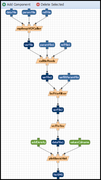
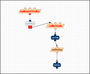
The tutorial consists on recreating one of the workflows introduced on the previous session. In particular, the BCFVarCaller workflow:
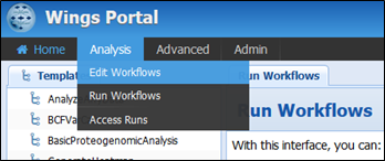
To create a new workflow, click on “Analysis>Edit Workflows”:
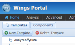
And click “New template” on the top left:
Action: Select a name for your new workflow template and click “OK”. Navigate to “Components” tab and add the “mpileupVCFCaller”, “callBcftools”, “vcftoTsv” and “plotBasicHist” components to the canvas:
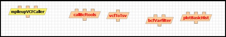
The components appear in red because they are not connected to each other. You can connect them by clicking on their inputs and outputs, which are represented with small squares on top and bottom. For example, the output of mpileupVCFCaller is represented in red in the figure below:
Action: Connect the inputs and outputs of the rest of the components until all of them appear in black, as in the figure below. Don’t forget to save it!!:
Congratulations! You have successfully created your workflow. Try to run it as shown in the previous session! (Analysis>Run workflows)
Hands on exercise 2: Creating abstract components in WINGS
Description: This exercise aims to guide you through the tasks associated to the creation of a workflow with abstract components, assuming the components exist in the library.
By the end of the previous exercise, we should have a workflow similar to the one in Figure 6. Note that inputs and outputs may have different names if they are dragged out in a different order. If you click on the “Layout” button, your workflow will be redrawn as shown in Figure 6.
But now imagine that we want to be more flexible and use other components instead of “callBcftools” for executing the workflow. In order to achieve this goal, we need abstract components. If we go to the component library tab, we can see that “callBcftools” is a type of “SNPIndelCaller”.
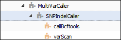
If we replace callBcftools with the SNPIndelCaller abstract component, now our workflow will be more generic. That means that we will be able to run the same workflow with both callBcftools or varScan components.
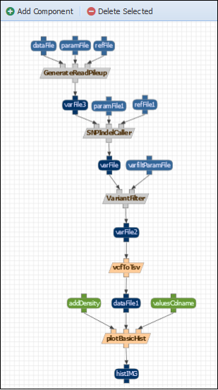
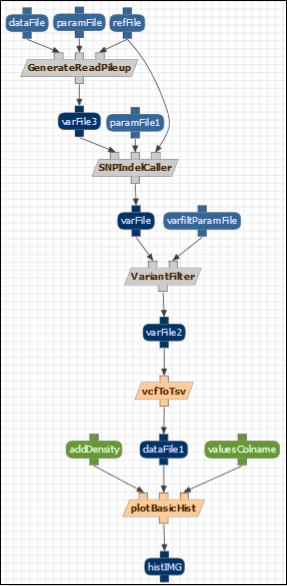
Action: A component can be deleted by selecting it and clicking “Delete Selected”. Delete the first three concrete components of the workflow and replace them with their abstract compontents: replace mpileUpCaller with GenerateReadPileUP; CallBcfTools with SNPINdelCaller and bcfVarFilter with VarianFilter. Save the results. The following workflow will be the result:
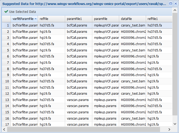
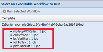
Now when executing the workflow (Analysis> Run workflows tab) and selecting the input data to use, WINGS will automatically recognize how the abstract components should be implemented. For example, if we plan the workflow selecting a vcfbarfilter parameter file, WINGS will select the mpileupcVCFCaller, callBcftools and bcfVarFilter steps for the implementation:
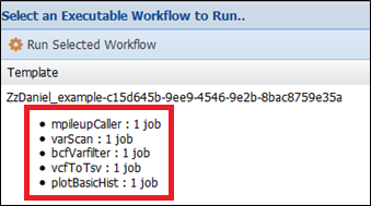
However, if we select the varscan parameter file and the mpileup parameter file:
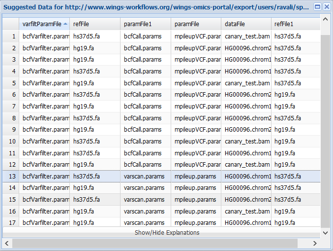
Then Wings will select the mpileupCaller, varScan and bcfFilter components for implementing the workflow.
Hands on exercise 3: Adding constraints to components in WINGS
Description: The purpose of this exercise is to guide you when editing and adding constraints to an existing component in the workflow library. Constraints are great to validate, select and propagate metadata through workflows. In this exercise we are going to add some constraints to the abstract workflow we created in the previous hands on exercise. Note that for the sake of simplicity, refFile is now shared by “GenerateReadPileup” and “SNPIndetCaller”.
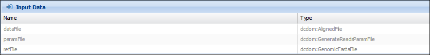
GenerateReadPileup and SNPIndel Caller are both VariantCallers. And we want to make sure that 1) the “varFile” output they consume and produce has a “GenomicBuildID” which refers to the same value. 2) both the “VarFile” and the “refFile” have the same GenomicBuildID. In the component (Advanced>Manage Component Types and selecting “GenerateReadPileup”), we can see that refFile is of type “GenomicFastaFile”, while dataFile is of type “AlignedFile”
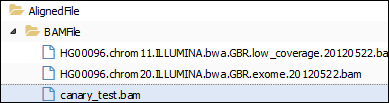
If we look for some data of these types in the Advanced> Manage Data tab and select a “AlignedFile”, we find different files (the files may vary according to what has been uploaded in the previous sessions):
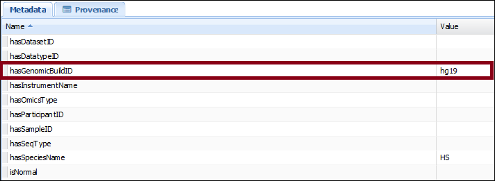
By clicking on one of them, we can see their metadata properties. For example, for canary_test.bam, we see that its “hasGenomicBuildID” value is “hg19”:
The first rule we will add to the workflow propagates this metadata for the GenerateReadPileup component. Action: Go to the Advanced>Manage Component Type tab, select “GenerateReadPileup”, click on the “Rules” tab and add the following text:
	[ propagateInputType: #This is the rule title
	(?c rdf:type acdom:GenerateReadPileupClass) #Begin body of the rule
	(?c ac:hasInput ?in1) (?in1 ac:hasArgumentID 'dataFile')
	(?in1 dcdom:hasGenomicBuildID ?val1)
	(?c ac:hasOutput ?odv)
	(?odv ac:hasArgumentID 'varFile')
	-> (?odv dcdom:hasGenomicBuildID ?val1) #Rule actions
	print(Asserted ?val1 as output of ?odv)
	]
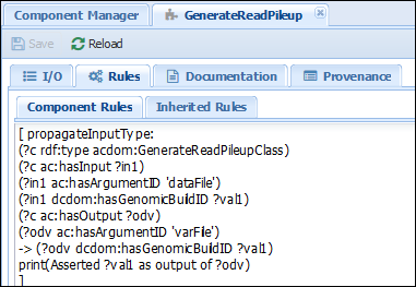
The rule indicates that if there is a component of type “GenerateReadPileup” in the workflow and has an input named “dataFile” with a genomicBuildID, then the output of the component should also have that genomicBuildID as well. Action: Plan the workflow (go to Analysis>Run and select your previously created workflow) and check that after selecting data, the metadata is propagated appropriately. A file with the metadata field “hasGenomicBuildID” has to be selected:
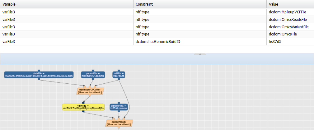
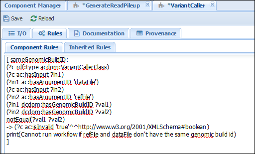
The varFile output from the GenerateReadPileup component (varFile3 in the previous figure) in the planned workflow should have the genomicBuildID value used by the “dataFile” input of GenerateReadPileUp. Now that metadata is appropriately propagated through the workflow, let’s create another rule. Action: copy the text below in the “Rules” tab of the “VariantCaller” component (in Advanced>Manage Component Types and selecting “VariantCaller”):
	[ sameGenomicBuildID:
	(?c rdf:type acdom:VariantCallerClass)
	(?c ac:hasInput ?in1)
	(?in1 ac:hasArgumentID 'dataFile')
	(?c ac:hasInput ?in2)
	(?in2 ac:hasArgumentID 'refFile')
	(?in1 dcdom:hasGenomicBuildID ?val1)
	(?in2 dcdom:hasGenomicBuildID ?val2)
	notEqual(?val1 ?val2)
	-> (?c ac:isInvalid 'true'^^http://www.w3.org/2001/XMLSchema#boolean)
	print(Cannot run workflow if refFile and dataFile don't have the same build id)
	]
The result should look as in the image below:
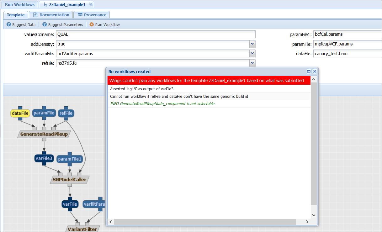
The rule states that if a component of type VariantCaller has an input “dataFile” and another “refFile”, then their “genomicBuildIDs” have to be the same. Otherwise, an error is triggered. Action: Check that when selecting input files with different genomicBuildIDs, the workflow cannot be executed. For example, the following configuration will lead to an error:
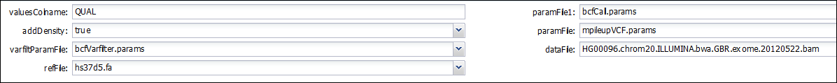
While the following one, using the same genomicBuildIDs, allows planning and executing the workflow:
Hands on exercise 4: Uplodading software to a component in WINGS
Description: The purpose of this exercise is to guide users on how to add components to WINGS.
WINGS creates workflows with components. Each component, as we have seen in the previous exercises, performs a main type of functionality. In order to upload your own components to WINGS, you must create a wrapper for your code. We will start with a simple example, adding a component that copies the contents of an input into the output. This can be done in the console with a single command:
cp input output
Action: Create a new component on your domain (Advanced>Manage Components) and call it “test”. Go to “Manage Components” and click on “Add component”. Assign it an input and an output. In my case, I chose “i1” and “o1” of type “BAMfile”. The inputs and outputs of your components are what we will use to concatenate components in workflows.
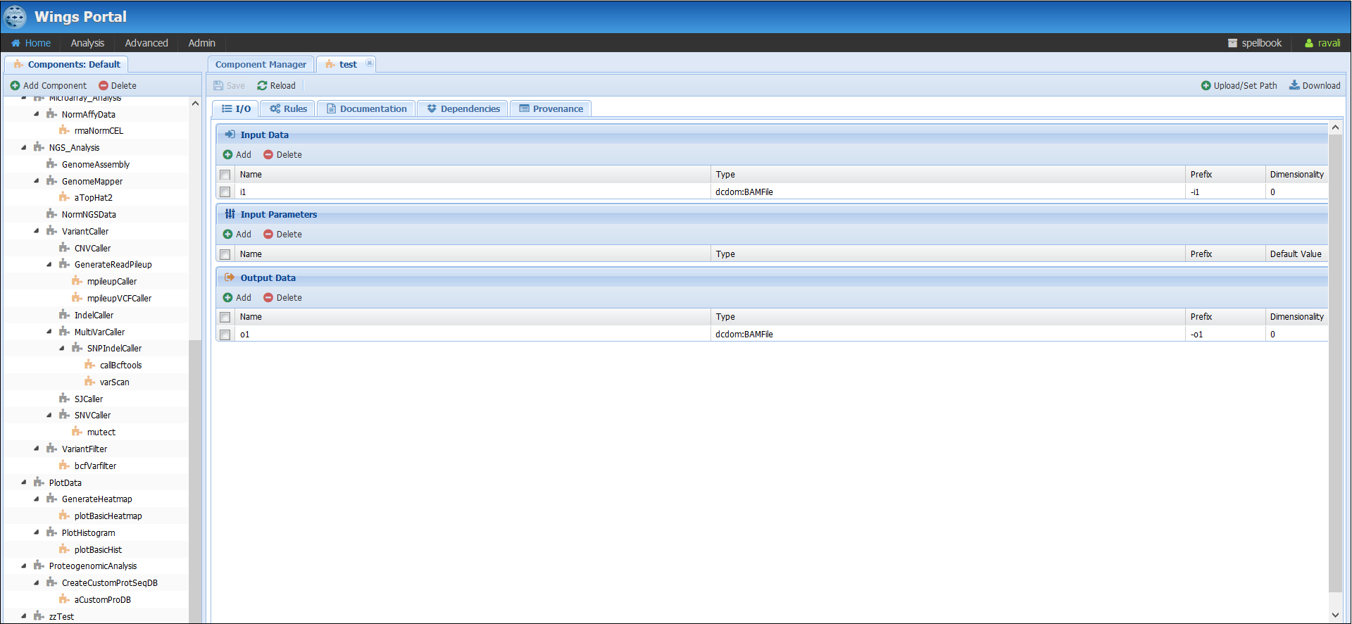
At the moment your component will appear in red. This means that no code has been uploaded for yet and therefore, the system cannot execute it. How to upload code for it?
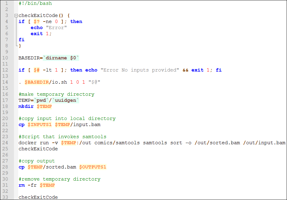
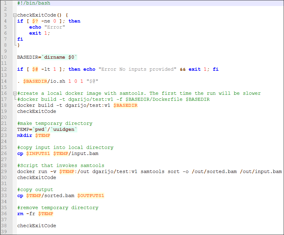
Action: Download the following template for adding components from this link. Open the zip file. You will find a run.sh shell script and an io.sh script. The run.sh script contains the copy command, and looks like the following:
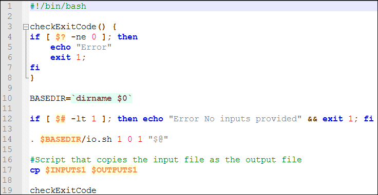
You can ignore everything except for line 14 and 17. Line 14 refers to the script io.sh used by WINGS to map the inputs we declared in the WINGS interface to the script. The line copies into three arrays ($INPUTS, $PARAMETERS and $OUTPUTS) the inputs, parameters and outputs used to be used by the current script. In this particular case we have 1 input, 0 parameters and 1 output. Therefore, we run io.sh with “1 0 1”. If we had a component with 3 inputs, 2 parameters and 1 output, we would run it with “3 2 1”. Line 17 executes the copy command we wanted to implement. In this case we are copying the input file in the output file, so we refer to them with their identifiers ($INPUTS1 and $OUTPUTS1). Now it is time to execute the component on WINGS.
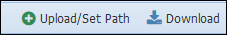
Action: upload your test component. You can upload by selecting the component and clicking on "upload", on the top right corner.
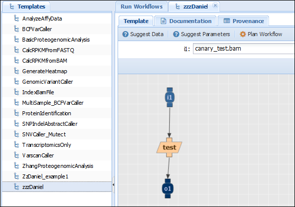
Check that the name of the .zip file is the same as the one you provided for the component in the system. Go to the template editor tab (Advanced>Edit workflows) and create a new template with your component. Go to the template browser (Advanced>Run Workflows) tab and plan your workflow to test that it works. The template should look similar to the image below:
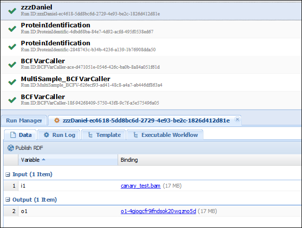
In the access results tab (Analysis>Access Results), you should see your run. If you click on the results of your execution (which should finish quickly if you didn’t pick up a big file), you can verify that the input is indeed the same as the output:
Congratulations! You have uploaded successfully your first component to WINGS! Now let’s explore something more complex. Download the code for the “MPileupCaller” component.
Action: Download the MpileupCaller code by selecting the component and clicking the “download” button on the top right of the screen:
Open the zip file and check the run.sh script.
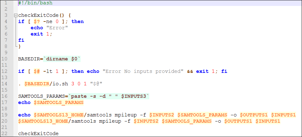
As you can see, line 14 invokes again the io.sh script. In this case, the component has 3 inputs and 1 output., so it is invoked with the “3 0 1” parameters. Line 20 invokes the SAMTOOLS software installed in WINGS. In this particular case, the $SAMTOOLS13_HOME variable is known beforehand and stored in the server. All the script does is to execute the mpileup software in samtools, stating how each input and output corresponds to the right place.
This approach for designing components allows you to execute any bash script that invokes any of the software tools installed on the server. If you write a script or create a self-contained executable file for your software (e.g., JAR file), you may even include them in your component zip file and invoke them in the run.sh script. Another way of installing software in WINGS is through Docker containers and images, further described below.
Dockerizing your software: Docker images and containers
Docker containers help replicating the environment and dependencies of a software, allowing us to execute it independently of the computing environment we are using at the moment. Docker handles two main concepts: containers and images. The images indicate how to set up and create an environment. The containers are the processes in charge of executing an image. In WINGS, containers can be created in two different ways: by using an existing image or by creating your own. Let's start with the simpler, which is to reuse an existing image.
Action: install Docker: https://docs.docker.com/engine/installation/. Try downloading a sample image to test its functionality with the following command:
docker run hello-worldYou should see the following on your screen:
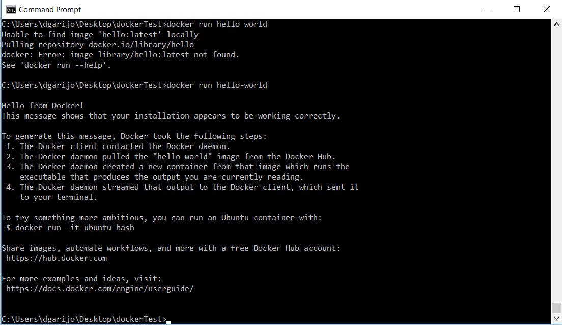
In the previous example we have created a container for the image “hello-world” and we have executed it.
Docker has a local repository where it stores the images we create. Some images are stored on default repositories online, such as the one we just retrieved. When we try to execute an image, Docker tries to find it online (e.g., on the Docker hub repository). If the system finds it, it will download it to our local repository. To browse over the images stored in your local repository, run the following command: docker images. At the moment you should only see the “hello-world” image.
Action: Download an Ubuntu image. Execute the following command:
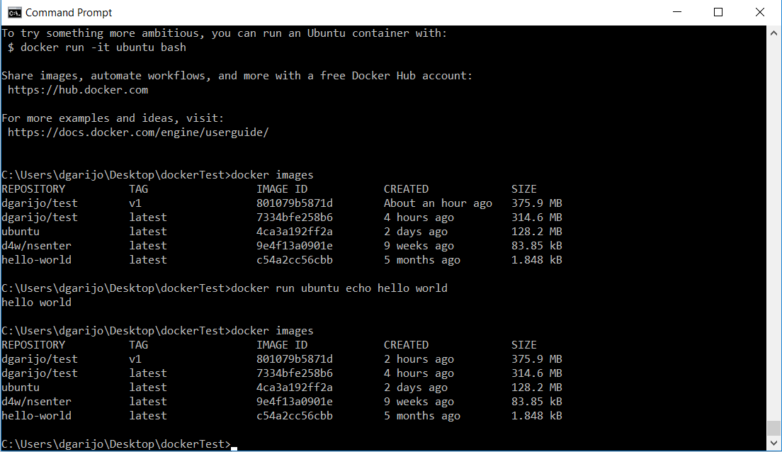
docker run ubuntuThis will install a whole clean Ubuntu image on your local repository. In order to test it, run any unix command like:
docker run ubuntu echo hello world
You should see something similar to the following:

Which is the same output you would obtain when executing that command in a terminal. If your software is widely used, someone probably will have created an image and posted it online. In this example we will show how to reuse an image for samtools, the software we have used for the mpileup caller component.
Action: Download a samtools image and test it on your local computer. After looking in docker hub, we can see that the official release for samtools is comics/samtools. Therefore, in order to import it to our local domain, we just have to perform the following command:
docker pull comics/samtoolsWhich will download the latest version. You can also specify the version by using the tag. For example comics/samtools:v1. Now you can try to execute the image locally, to see whether it works. Let's try to invoke the mpileup software:
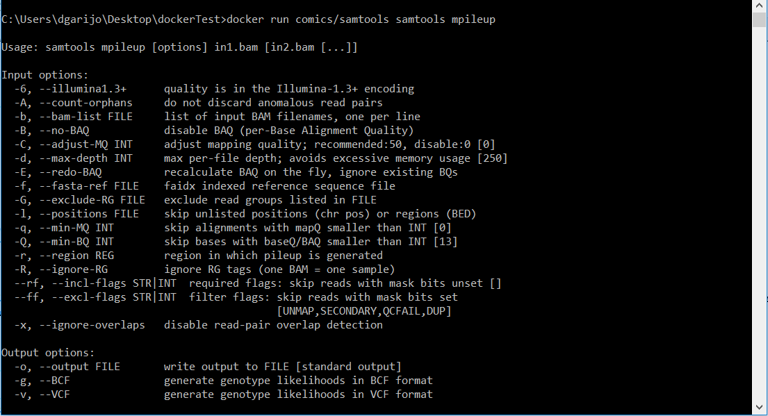
docker run comics/samtools samtools mpileupSince we have not specified any inputs, you will see the following on screen.
Action: execute the following command:
docker run -v PathToFolderYouWantToShare:/out comics/samtools samtools sort -o
/out/sorted.bam /out/inputFileToSort.bam
Where the PathOfTheFolderYouWantToShare is the folder where you have your input file ("inputFileToSort.bam"). This will result in a sorted file ("sorted.bam") of the input file “inputFileToSort” in the folder "PathToFolderYouWantToShare". Now that we have tested our image locally, we should test it in Wings.
Action: Create a component in Wings and use the Docker image to invoke it (you can find a component template in this link). The component should look similar to the picture below:
The script is similar to the console command we have executed locally, but copies the input to a temporary folder. This way if we have ten instances of the component at the same time, they will read the appropriate temporary folder. The temporary folder is mounted in WINGS using the "-v" Docker command we have used previously. The outputs are copied to the corresponding WINGS output (using "cp"), and the local files are removed ("rm" command).
Congratulations! you have a "Dockerized" component in WINGS! However, what would happen if you want to create your own image? We address this in the next section.
Creating Docker files
The first step is to build an image for the software we want to install.
Action: create a file and add the following text (the tabs indicate the commands continue in the previous line):
from ubuntu
MAINTAINER add yourself here emailgoeshere@example.com
RUN apt-get update && apt-get install -y python unzip gcc make bzip2 zlib1g-dev
	ncurses-dev
COPY samtools-1.3.1.tar.bz2 samtools.tar.bz2
RUN bunzip2 samtools.tar.bz2 && tar xf samtools.tar && mv samtools-1.3.1 samtools
	&& cd samtools && make
ENV PATH /samtools:$PATH
The file should look similar to the following one:
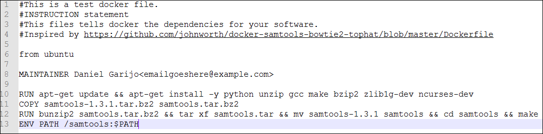
This image modifies the Ubuntu image we downloaded before, installing python, unzip, gcc, make, bzip2, zlib-dev and ncurses-dev, which are packages used by samtools. Thanks to this, we will have access to those commands from our Linux terminal in our container. The second command copies the software we want to install into the container (download it from https://sourceforge.net/projects/samtools/files/samtools/), unzips it and compiles it, adding “/samtools” to the system path.
Action: Build the image you have created and check that docker adds it to the local repository. This may take a little time:
docker build -t youruser/nameOfImage -f pathToDockerFile .youruser/nameOfImage is just a way to tag the images you create. In my case I named it dgarijo/test:v1. Later, when running the image as a container, we will use this name. The -f option points to the docker file you want to build as an image. This flag is optional: if you don't include it, it will search on your local folder. Also, in some cases there are known issues. If you run into any trouble, just use:
docker build -t dgarijo/test:v1 DIRECTORY .Where the "DIRECTORY" contains a docker file called "Dockerfile". When Docker finishes, you should see a list of your images, similar to:
Congratulations! You have just added successfully your image to your local repository. These images can be committed and exported in online repositories for others to download, as we have seen before. Now that our image is in our local repository, let’s run it:
Action: Execute the following command:
docker run IMAGENAME samtools/samtools mpileupwhere IMAGENAME is the name you have to your image (in my example, dgarijo/test:v1). As a result, you should see the following:
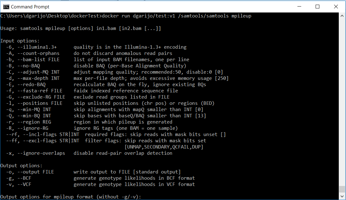
Since we tried to execute the mpileup software without any input files, the system shows the samtools help interface. In order to be able to share the inputs files with our docker container, we need again to mount a volume using the “-v” option.
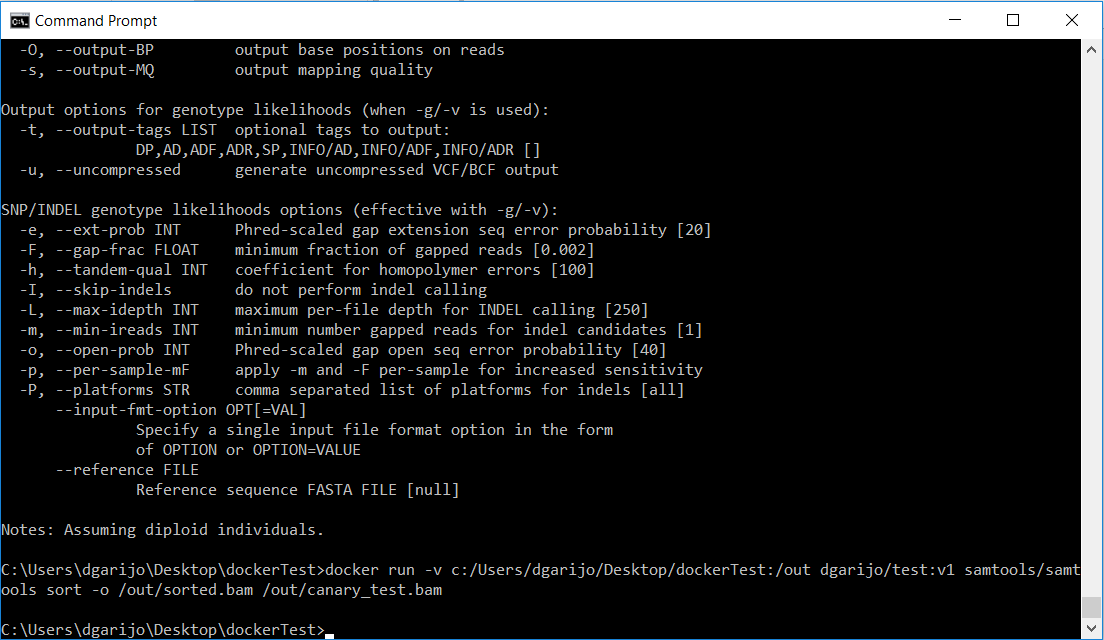
Action: execute the following command:
docker run -v PathOfTheFolderWithTheBamFile:/out nameOfYourImage samtools/samtools
sort -o /out/sorted.bam /out/canary_test.bam
After a few seconds, you should see that the program ends, and a new file “sorted.bam” has appeared in your shared file.
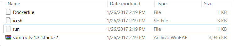
Congratulations! Your container works as expected. Now you just need to add your dockerfile to the component and tell WINGS to execute your Docker file. Be sure to include the samtools zip file as well! Your folder should look as in the image below:

This page was created by Daniel Garijo, with the help of Varun Ratnakar. It is licensed under a Creative Commons Attribution-NonCommercial-ShareAlike 2.0 Generic License.